How Almco Plumbing Efficiently Replaced the Gas Pipeline of an Apartment Complex: A Step-by-Step Process, Safety, and Environmental Considerations
A red flag from gas services is a serious issue for any homeowner, as the lack of gas significantly complicates daily life. Therefore, Almco specialists immediately responded to a client’s request in Spring Valley, where a gas leak was detected in the main pipeline on their property. The case below describes each stage of the pipeline replacement, explains the advantages of the chosen materials and methods, and emphasizes the minimization of environmental impact during the repair, including the use of eco-friendly materials.
Contents
Technologies & Services

The Client’s Problem & Reasons for Replacing the Gas Pipeline
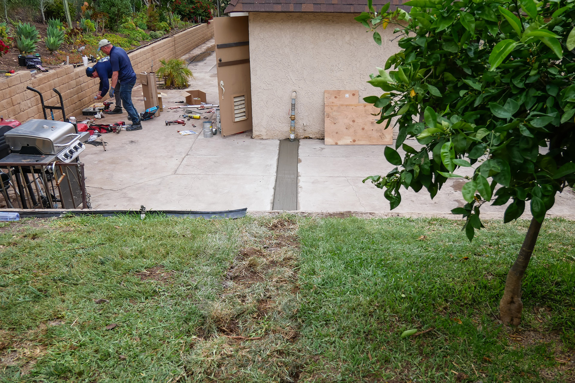
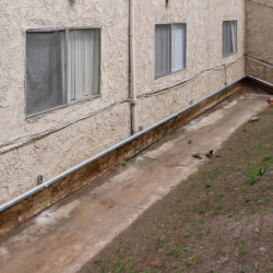
A homeowner in Spring Valley contacted Almco Plumbing after receiving a red flag from the city gas service, which prohibited use of the gas system in their apartment complex. Gas service workers detected a gas leak, one of the most serious issues in gas pipeline operation, requiring urgent action to fix it.
A manometer test on the gas pipe outlet showed insufficient pressure in the gas supply system. This occurred because the existing gas main was assembled from CPVC pipes 40 years ago, leading to gaps and gas leaks over time. The pipeline was made of CPVC pipe sections of varying diameters, not intended for gas systems. Additionally, this pipe was connected to a standard galvanized pipe, which does not meet safety standards.
General Project Description, Materials, and Installation Methods


Almco specialists needed to replace the entire gas main with new thick-walled steel pipes, install several new valves and a manometer, and connect the system to the water heater and city gas supply. The project’s goal was not only to restore the gas pipeline’s functionality but also to minimize environmental impact.
To speed up the repair process, the gas main replacement project was divided into three stages:
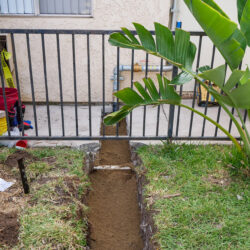
- Replacing the pipeline in the trench on the lawn
- Replacing the pipe in the concrete trench near the house
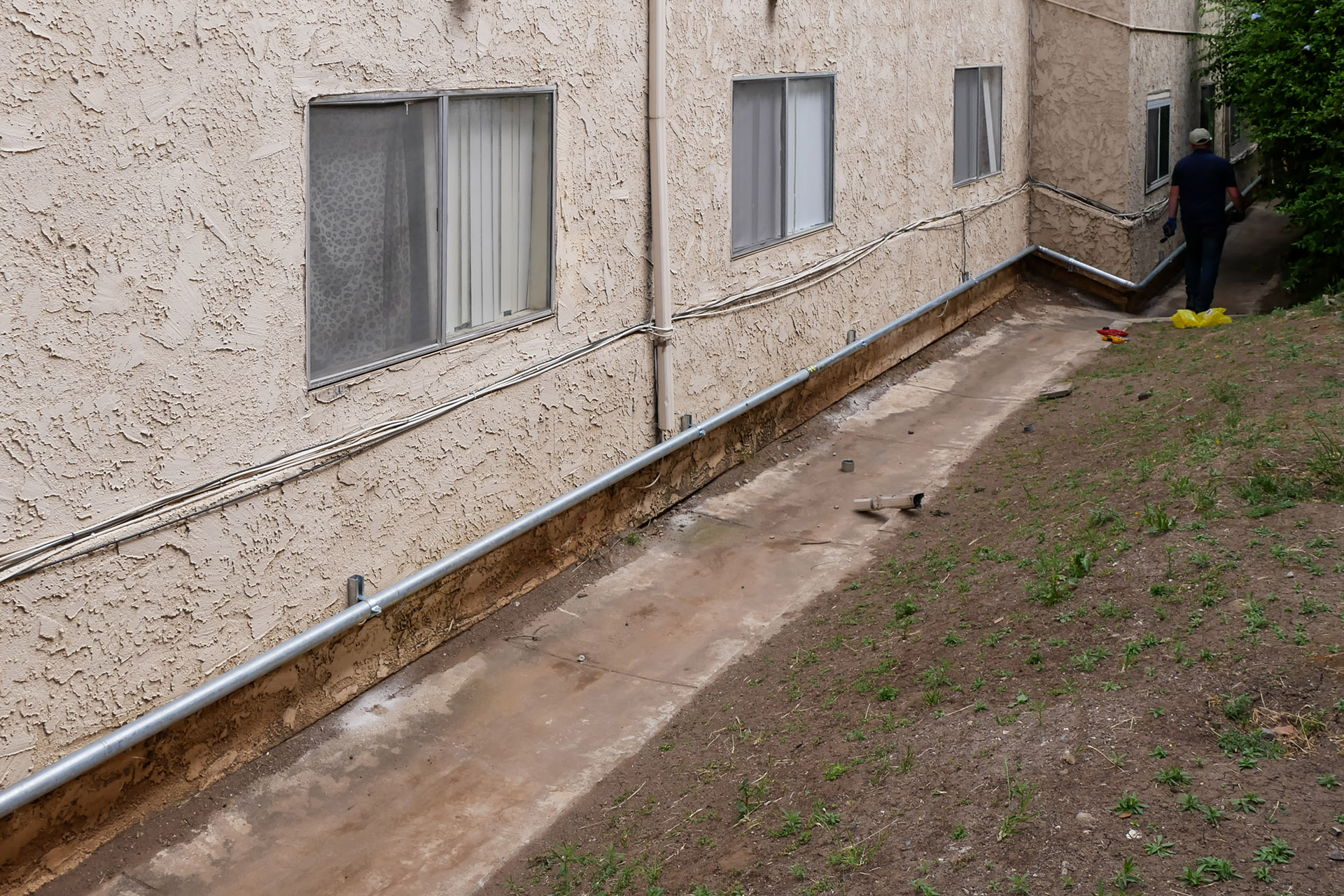
- Installing the new pipe along the house wall
Each stage used modern technologies and materials to reduce environmental pollution. Almco obtained a city permit for all gas network-related work.
Pipeline Materials

Galvanized thick-walled steel pipes
Galvanized thick-walled steel pipes were used for the above-ground pipeline, while low-pressure polyethylene pipes were used underground. Polyethylene gas pipes have high flow capacity, elasticity, and durability (over 100 years), minimizing the risk of future leaks and replacements. They are environmentally safe, resistant to external factors, and do not release toxic substances that pollute soil and water.
Installation Methods
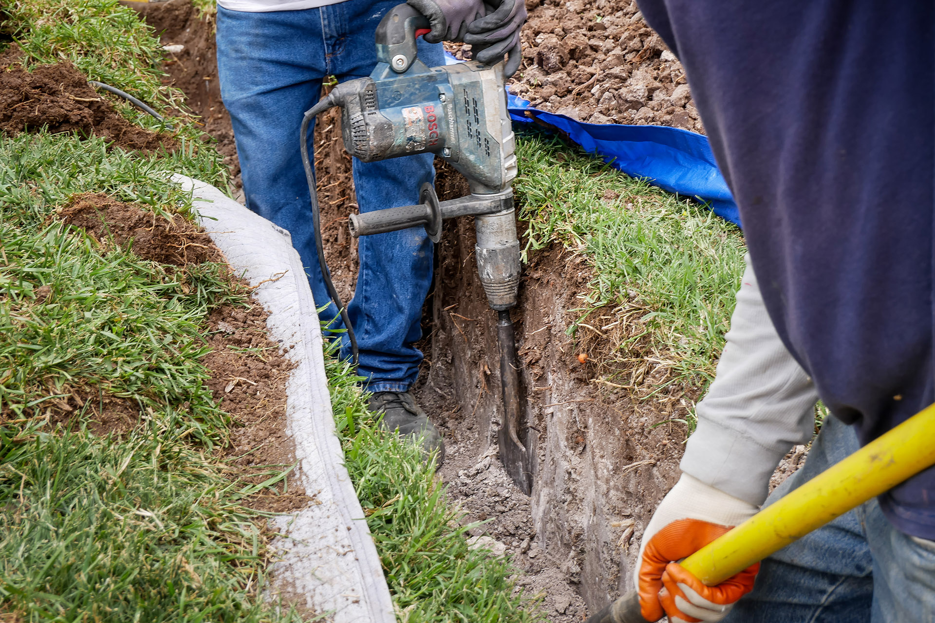
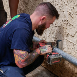
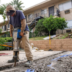
Hand tools, such as a jackhammer and a disc saw with water supply, were used to dismantle concrete structures, significantly reducing dust.
The new pipes were installed using Mega Press, allowing the 2-inch steel pipe system to be assembled in one day without threading. Teflon and pipe dope were used on threaded connections near the gas meter to ensure long-term tightness.
All trenches were backfilled with multi-purpose soil, creating a drainage layer and preventing water stagnation, helping to maintain soil balance.
Step-by-Step Process of Replacing the Gas Main
Below is a detailed description of the work carried out.

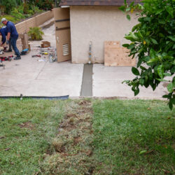
To minimize damage to the property and maintain cleanliness during repairs, Almco workers used special tarpaulins to place the excavated soil.
The sod was carefully removed in one piece where the trench would pass, allowing it to be replaced later to restore the lawn’s appearance.
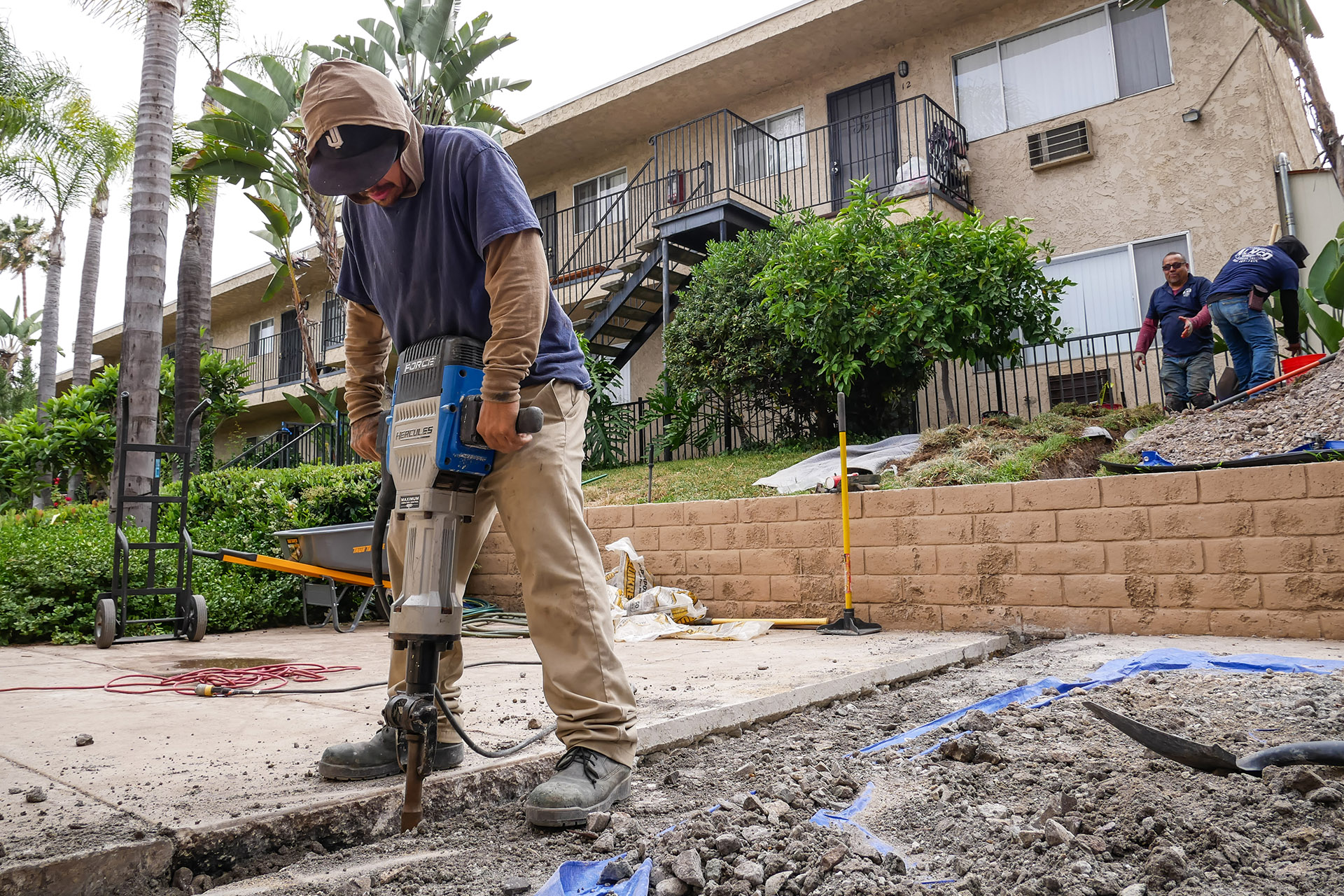
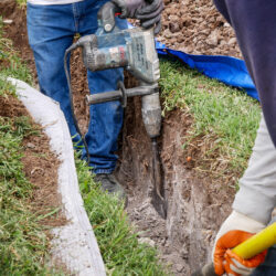
Hand tools, shovels, and an electric jackhammer with a wide, sharp chisel were used to remove roots while digging the trench on the lawn.

The concrete pavement near the house also needed to be dismantled where the gas main ran. An electric handheld disc saw with a diamond blade was used for initial marking of the future trench.
To minimize dust, water was supplied to the cutting channel and the city water supply, cooling the cutting disc simultaneously. The dismantled concrete was broken into small pieces with a jackhammer and placed on a tarpaulin for later disposal.
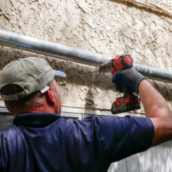
After completing all preparatory work, the team began installing the new gas main.

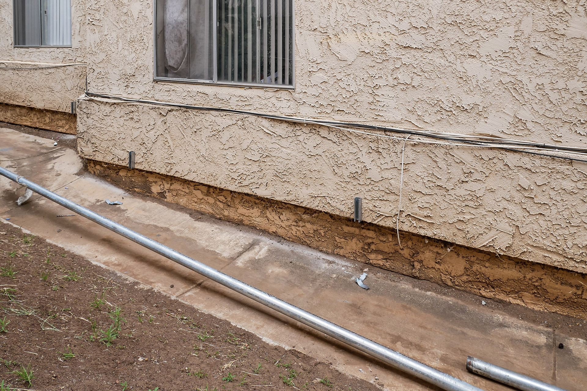
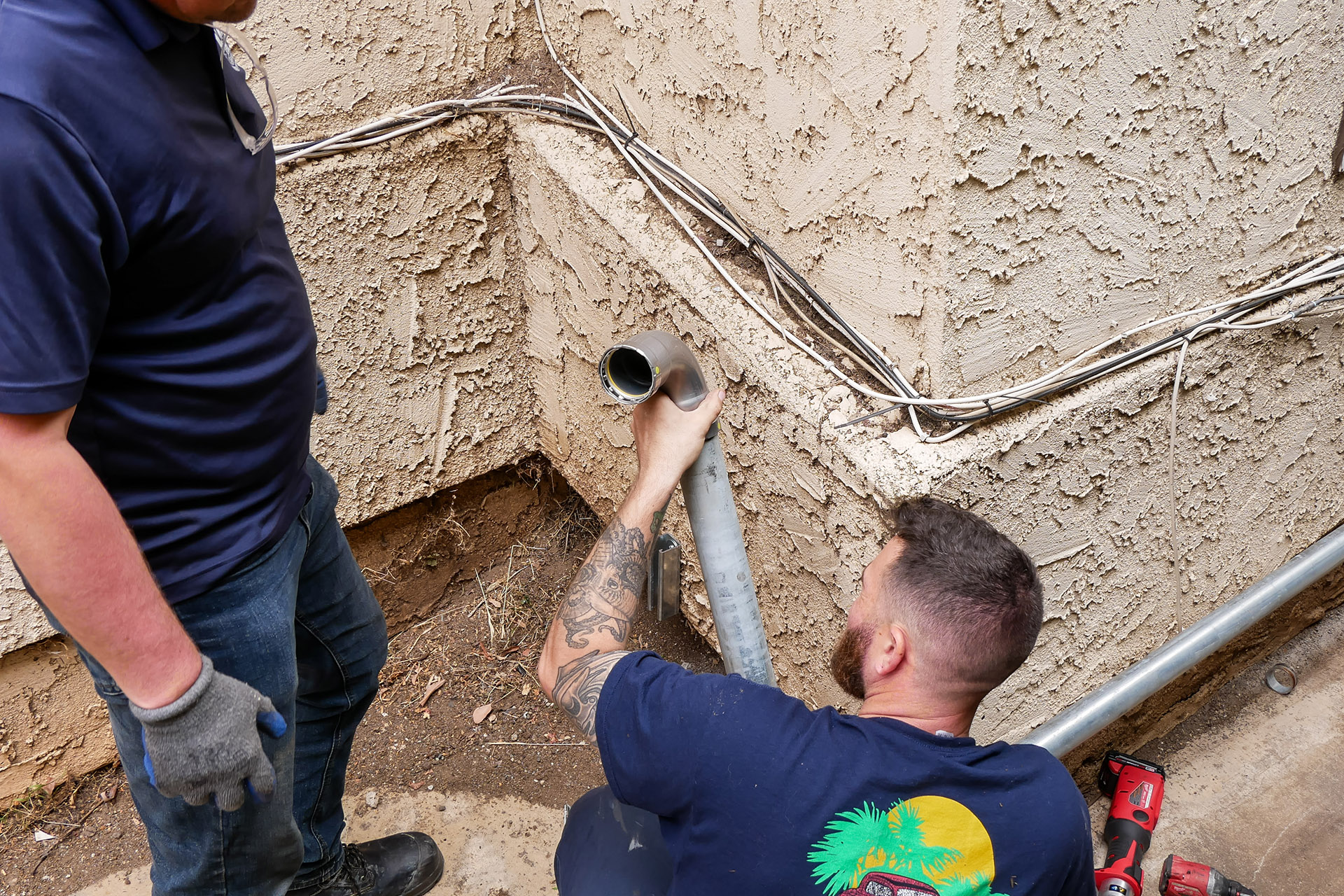
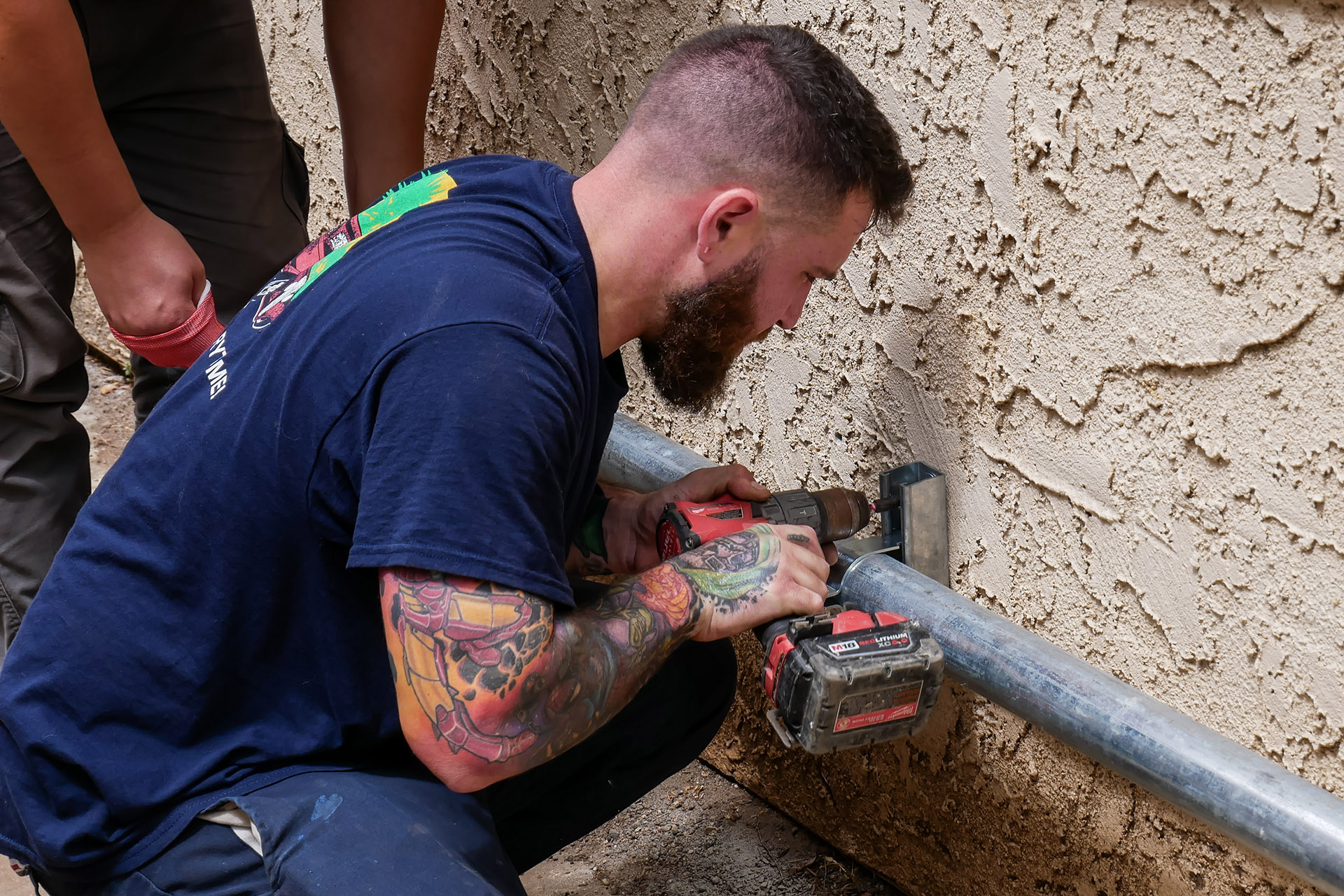
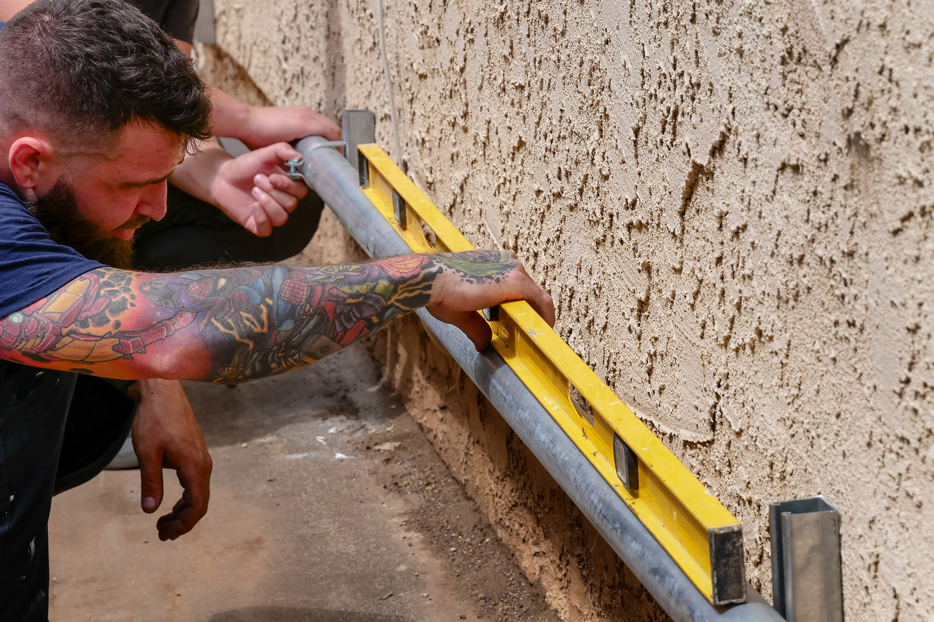
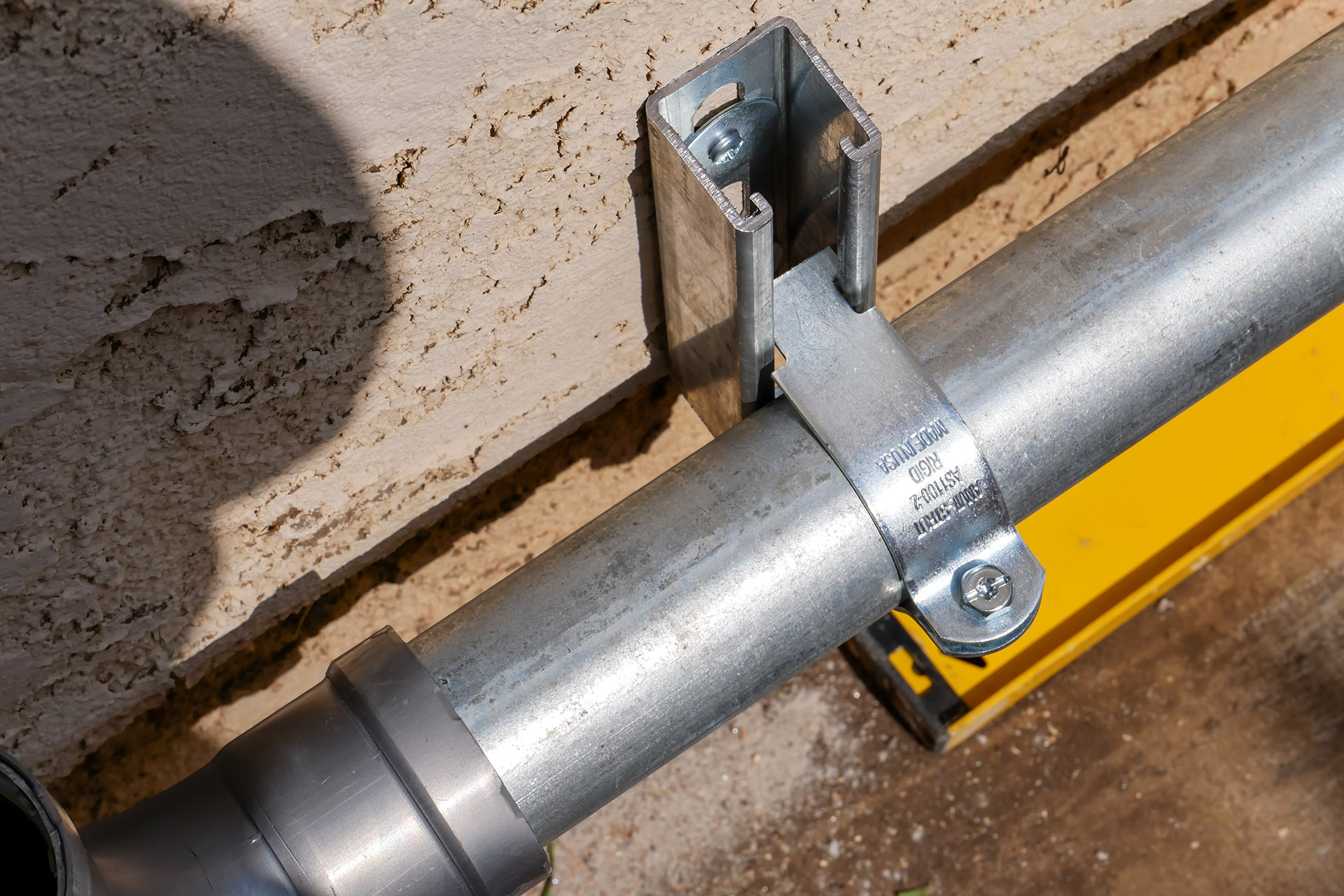
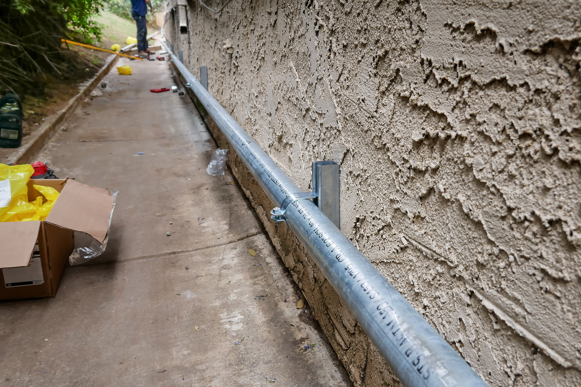
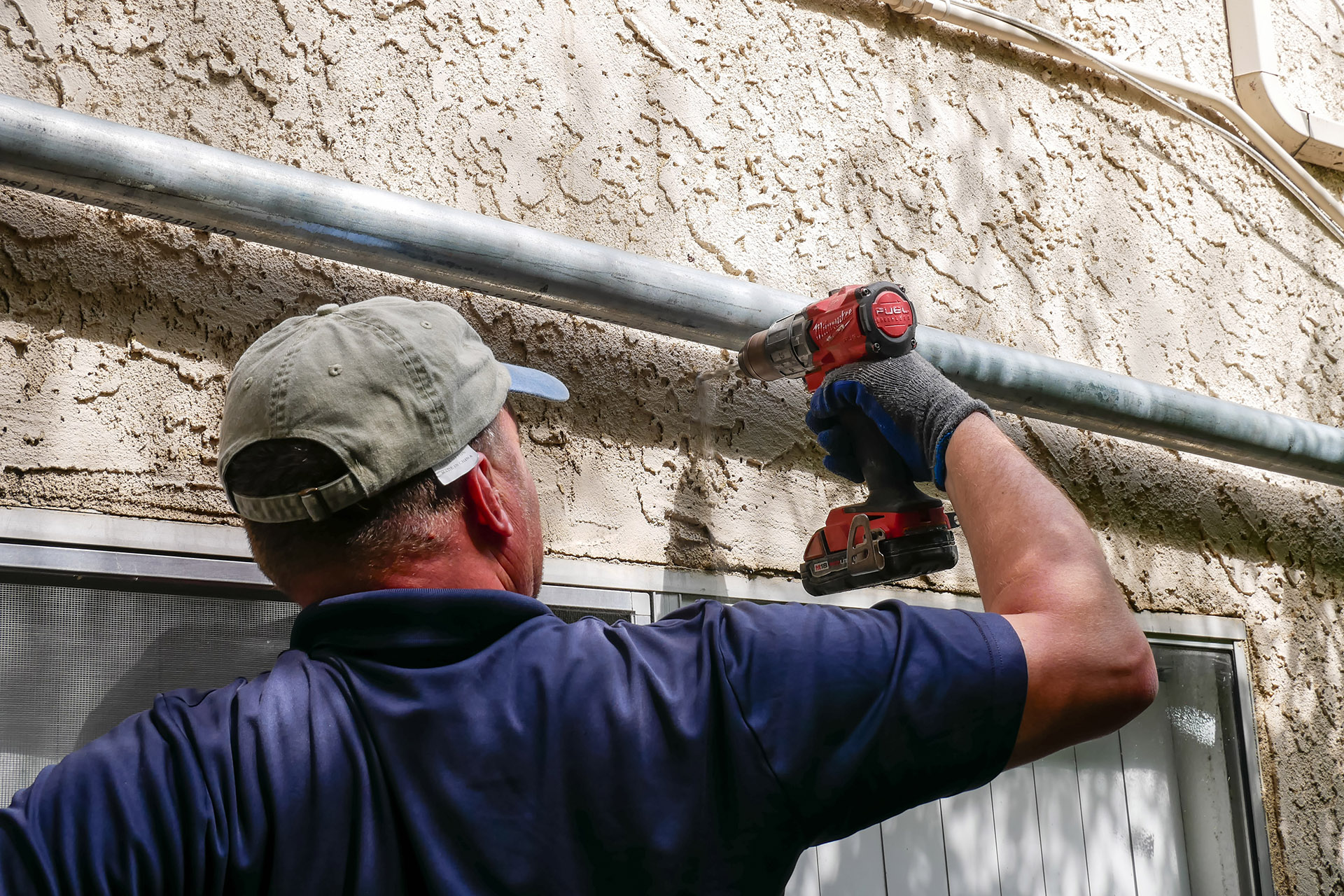
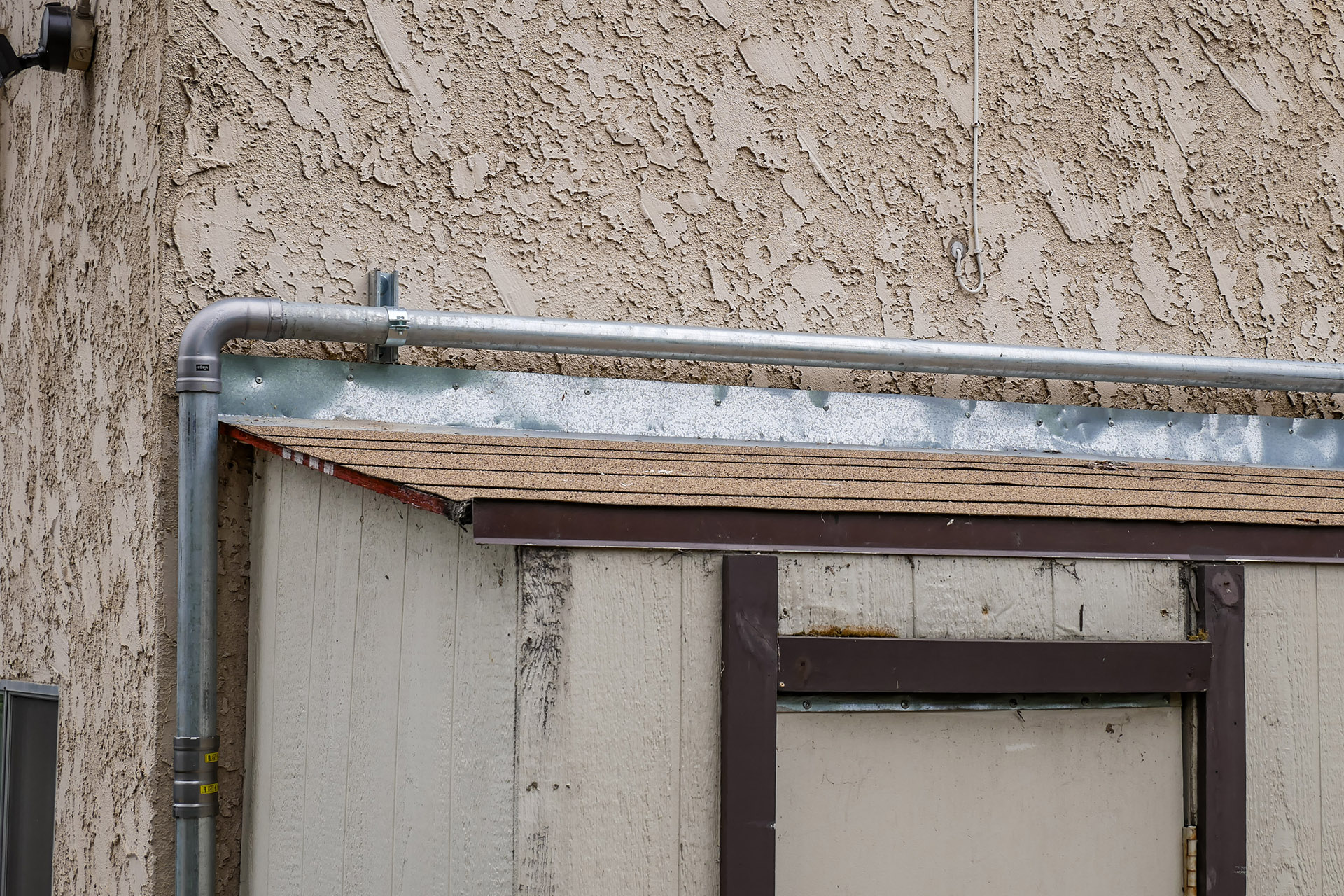
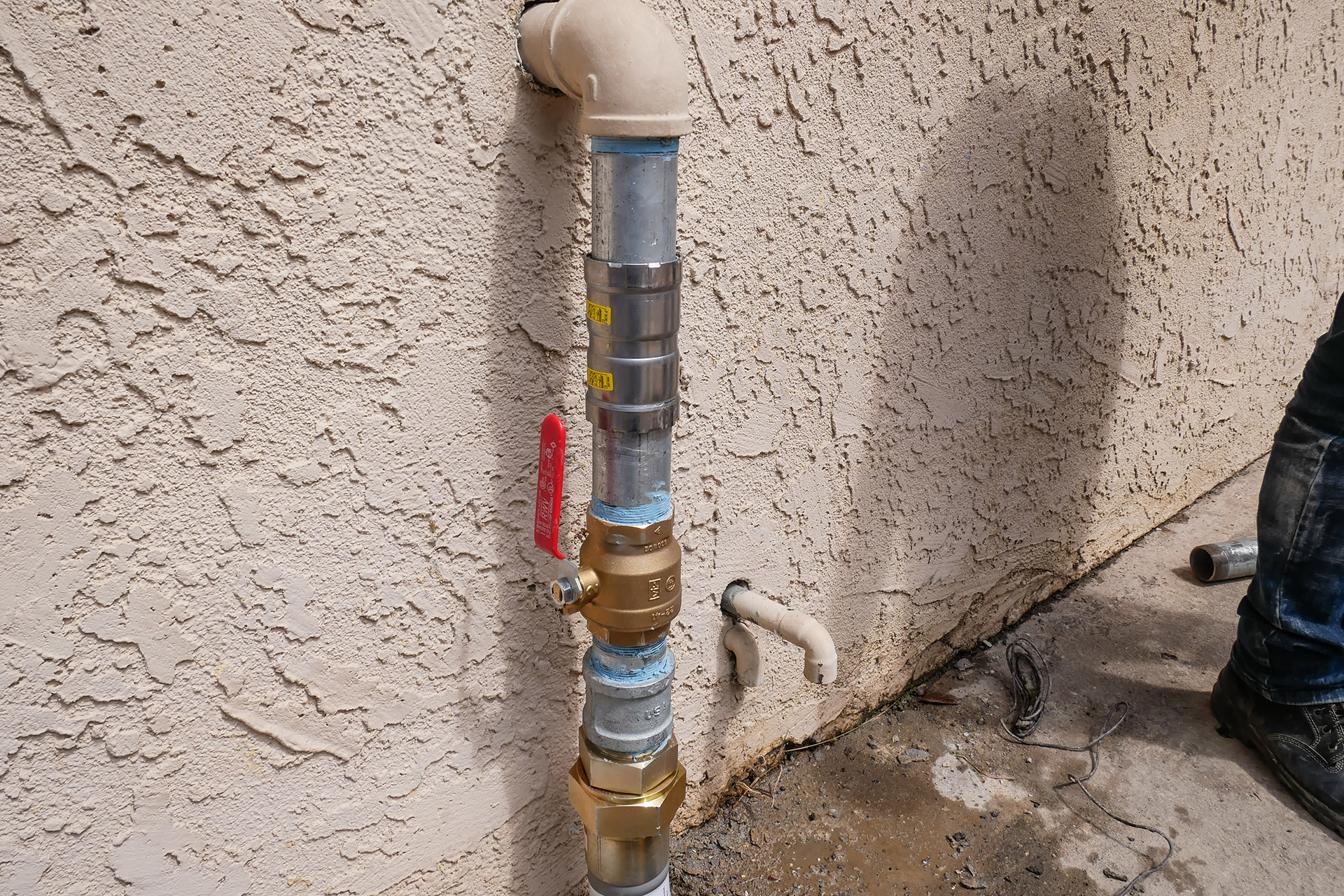
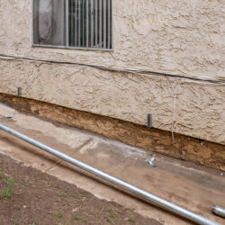
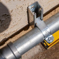
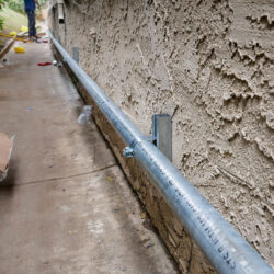
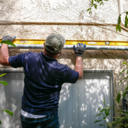
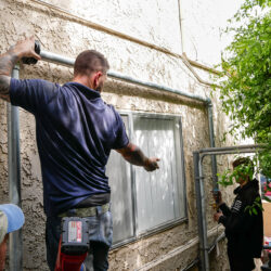
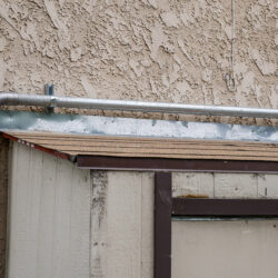
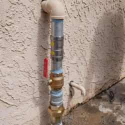
Using fixing clamps and a galvanized steel profile, the new gas main was secured to the house wall.
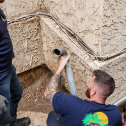
Metal elbows with a 90-degree bend were used for corners. They were attached to the pipe with fitting connections and additionally sealed with Mega Press. This installation method ensures the quality of the work and the durability of the gas main.
The same installation method was used on straight sections of the pipeline to increase the installed pipe’s length.
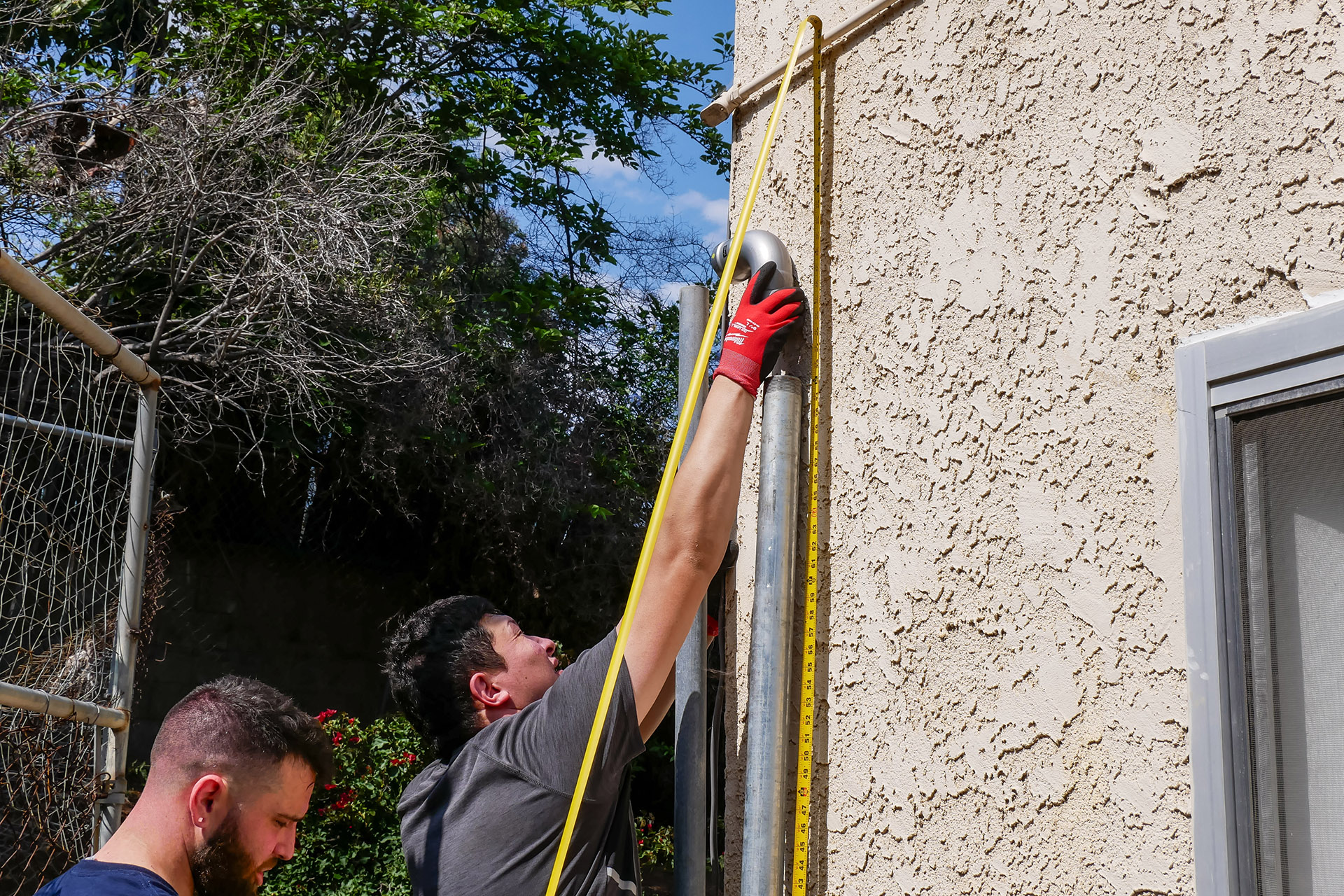
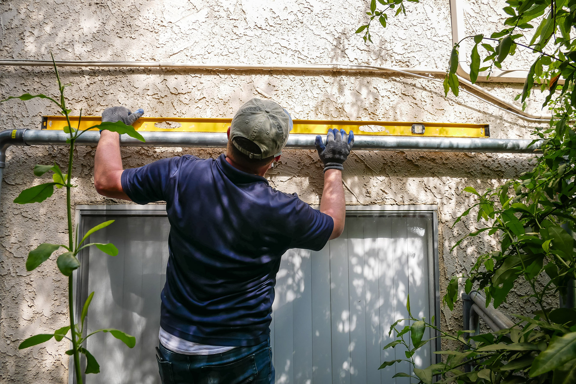
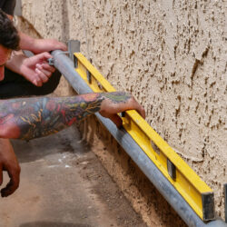
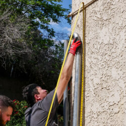
The entire pipeline installation was performed in horizontal and vertical planes, without tilting, which is not only technologically but also aesthetically correct. A vertical plumb line and a construction level were used for this purpose.
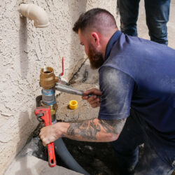
After installing the gas pipe along the house wall, it was connected to the gas meter, and a vented-type shut-off valve and a test manometer with a scale up to 15 PSI were installed. Thus, the new gas main was ready for city service inspection.

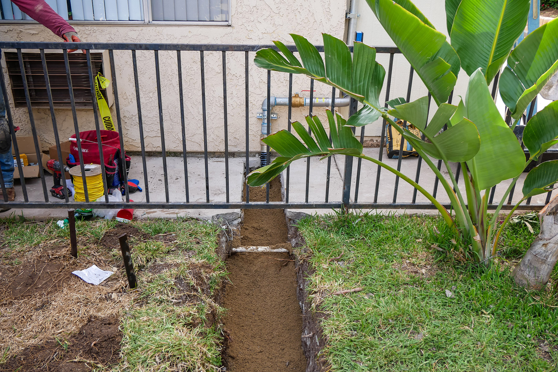
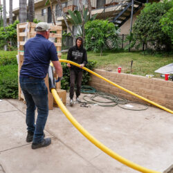
In repair areas 1 and 2, Almco Plumbing workers leveled the trench bottom, compacting it with a tamping machine. Horizontally, using a construction level, they installed a low-pressure polyethylene gas pipe. These pipes have the following advantages:
- Operating pressure up to 90 PSI
- Low thermal conductivity
- High flow capacity (30% higher than steel pipes)
- Elasticity
- Durability, 100+ years of operation
- Eco-friendliness—the material does not pollute soil and water, does not decompose, and does not release harmful substances
This section of the main was connected to the pipeline secured to the house wall using Viega fittings. A vented-type gas shut-off valve was also installed in this area. The pipe section to be laid under concrete was additionally placed in a polyurethane damping sleeve to protect it from possible deformation.

The next step was testing the gas main. The company’s engineer connected the gas main to the city system and tested the new main at an operating pressure of 10 PSI for 15 minutes. The pressure was the same at the inlet and near the gas meter.
The connection points were also tested with a gas analyzer for possible leaks, and no leaks were found. This means the homeowner no longer needs to fear inspection by SDG&E (San Diego Gas and Electric).
Important! To successfully pass the city inspector’s check, it is necessary to provide the gas service with access to the house so they can ensure there are no gas leaks on kitchen stoves, boilers, and water heaters. If gas service workers do not have access to all gas appliances in the house, they will not open the gas supply to the house.

Upon completing the gas main replacement, the excavated soil was layered back into the trenches. Each layer was then compacted to evenly distribute the soil in the trench and reduce the possibility of voids. This eliminated the risk of the lawn sinking during watering or rain. The previously removed top layer with grass was then laid back.
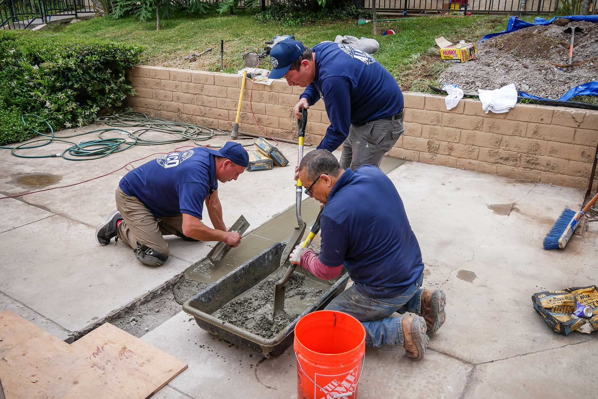
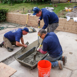
Similar work was done on the concrete-covered area. The trench was then filled with fresh concrete and finally leveled by hand with a construction trowel. After the concrete had fully hardened, the project was ready for delivery to the client.
Since all the soil and sod were placed on tarpaulins during dismantling, there was no construction debris, speeding up the completion of the work. The division of the entire work scope into sections also positively impacted the speed of the gas main replacement.
Environmental Aspects of the Project
Using tarpaulins to store excavated soil and sod prevented site contamination and minimized construction waste.
The sod and soil were returned to their original locations, preserving the site’s original appearance and preventing soil erosion. Compacting each soil layer minimized voids and prevented future lawn sinkholes.
The new pipe was laid along the wall, not underground, to minimize waste during the dismantling of the concrete covering around the house. This solution also saved resources when pouring new concrete.
Polyethylene pipes were chosen for their durability and eco-friendliness. They help reduce the carbon footprint due to lower energy consumption during production and long service life.
From an environmental perspective, the project achieved several goals:
- Soil and landscape preservation
- Waste minimization
- Use of durable and eco-friendly materials
The gas main reconstruction in Spring Valley demonstrated that modern technologies and approaches not only ensure the safety of future operation but also maintain environmental sustainability. Using eco-friendly materials, minimizing waste, and reusing resources are important steps toward reducing the environmental impact of construction projects.